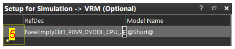
Power Net 與 VRM 設定
P0V9_DVDDL_CPU
需要 enable 這些 power net,以完成連線並納入此 PWR rail 上的所有 caps:
P0V9_DVDDL_CPU_R
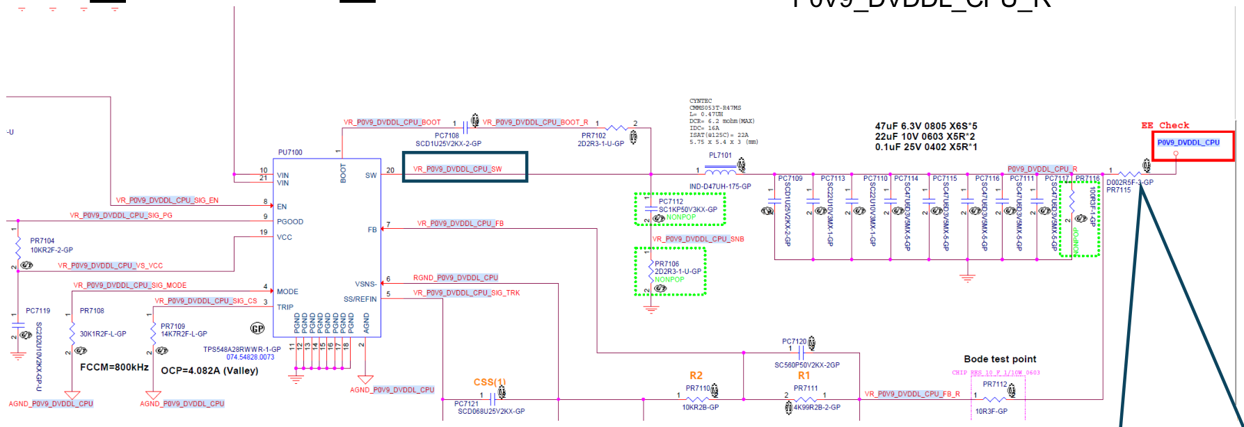
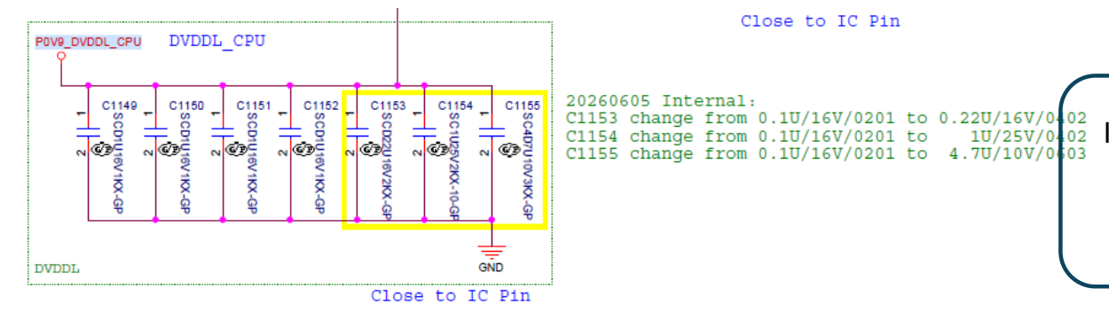
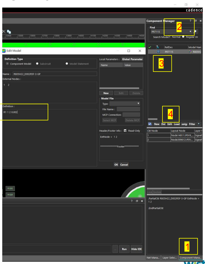
此案例中,Inductor PL7101 與 P0V9_DVDDL_CPU 之間有 resistor PR7115。因此需在 Component library 中 enable,並填入 resistor value,如第 11 頁所示。
8. Power Net selection for Simulation
- 選擇
Net Manager。 Disable All Net。
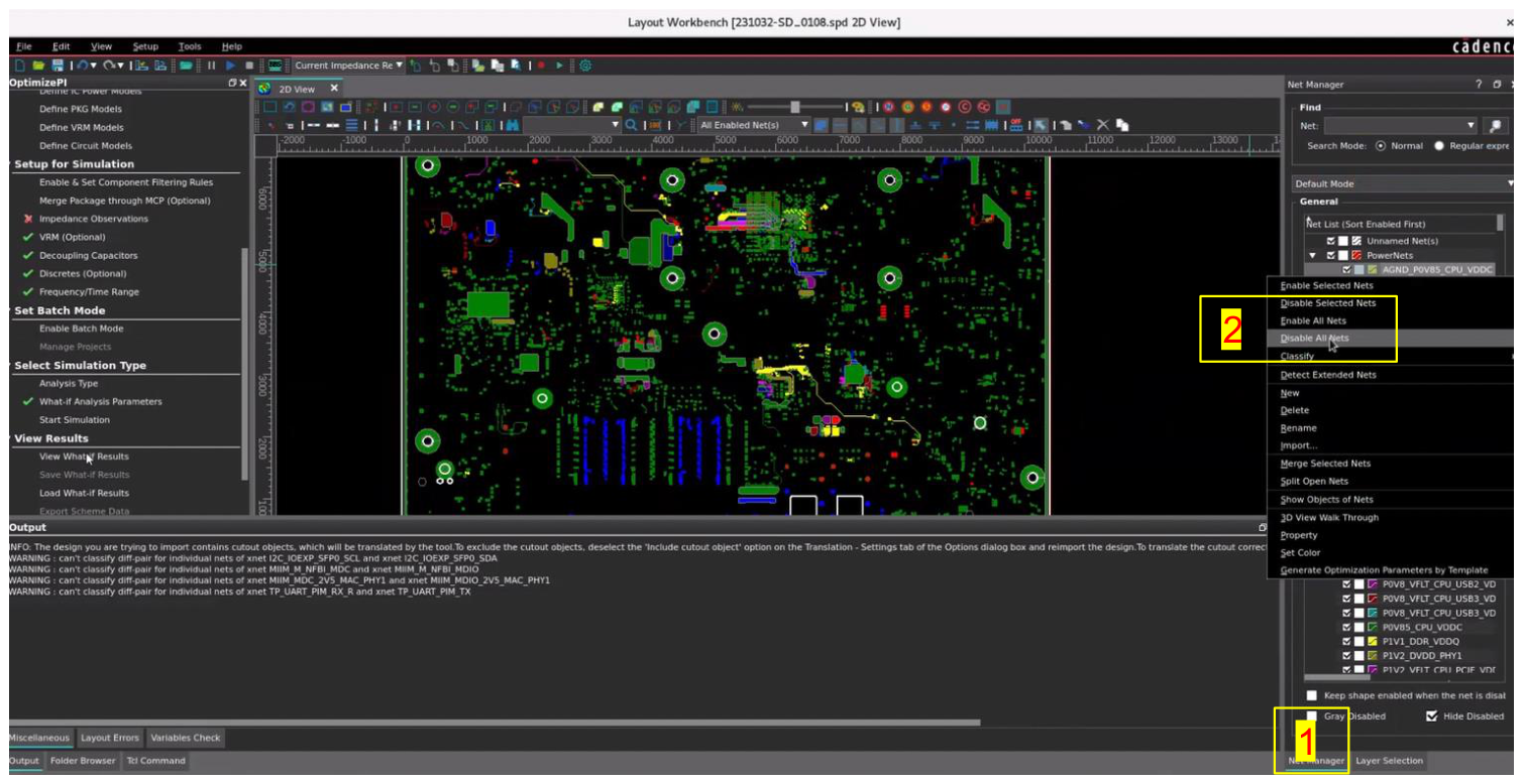
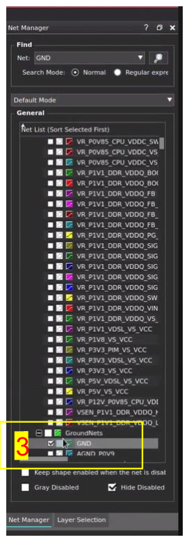
- Find and Enable GND Net。
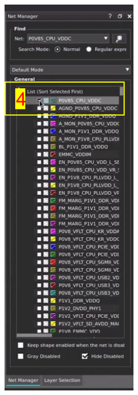
- Find and Enable PWR Net,例如
P0V85_CPU_VDDC。
9. Setting Up NewCkt for VRM Setup
需要 enable 這些 power net,以完成連線並納入此 PWR rail 上的所有 caps:
P0V9_DVDDL_CPU_R-
VR_P0V9_DVDDL_CPU_SW -
Enable
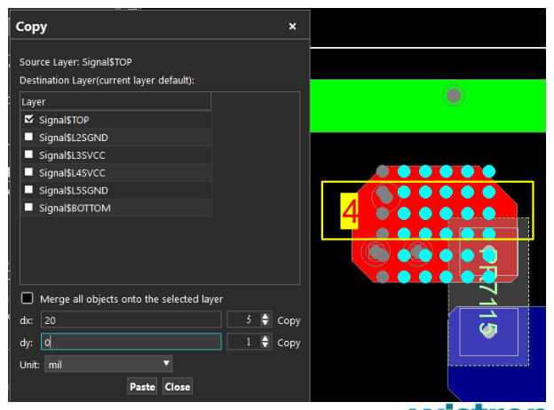
Node View。 - 在 PWR 與 GND node 上 Add node。
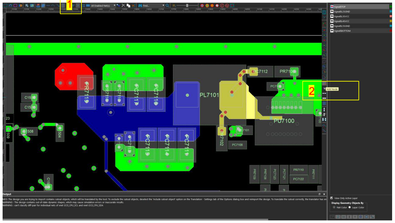
- Add node 後按
Ctrl+C,在跳出的視窗中設定dx = 0,在 Y-axis 加入 node。
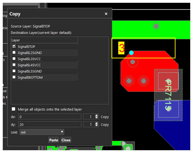
- 選擇所有 node 後按
Ctrl+C,在跳出的視窗中設定dy = 0,在 X-axis 加入 node。
10. Setting Up NewCkt for VRM Setup
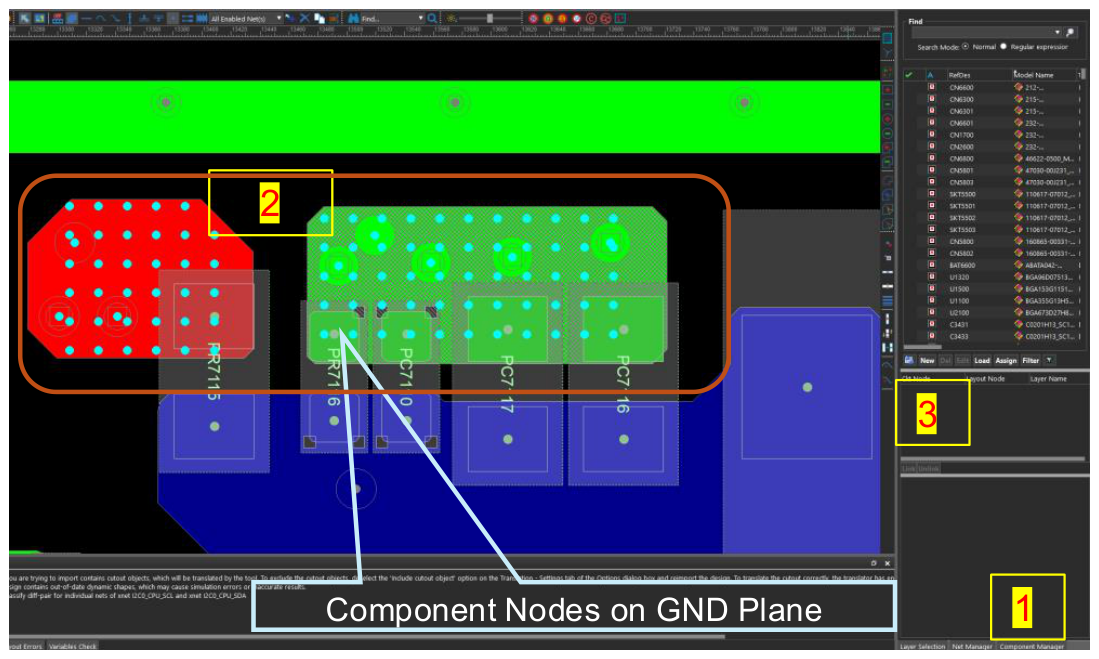
- 開啟
Component Manager:Alt+C。 - 選擇 PWR 與 GND plane 上的所有 node,但排除 GND plane 上的 component nodes。
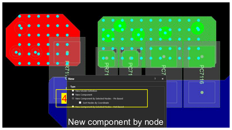
Create New Component。New component by node→OK。
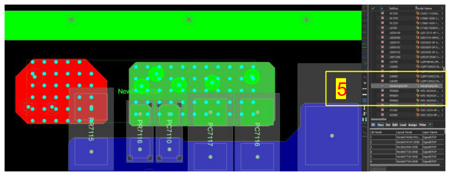
- 建立
NewEmptyCkt1,後續用於 VRM setup。
11. Setting Up the VRM on the Power Rail
- 開啟
Component Manager:Alt+C。 - 找到 Resistor
PR7115。若 PWR 與 regulator inductor 之間存在 resistor,需用來建立連線並避免 regulator component 的 open ckt error。 - Enable 此 component。
- Edit 此 component。
- 在 Definition 輸入:
R1 1 2 0.002
[ResistorDes 1 2 Resistive value]
12. Setting Up the VRM on the Power Rail
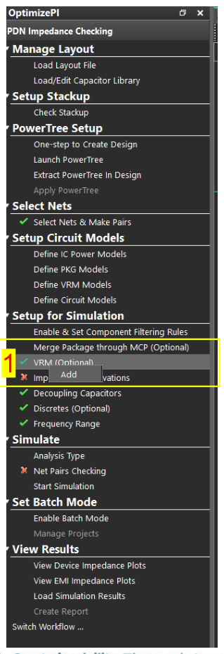
VRM→ Right click → Add。
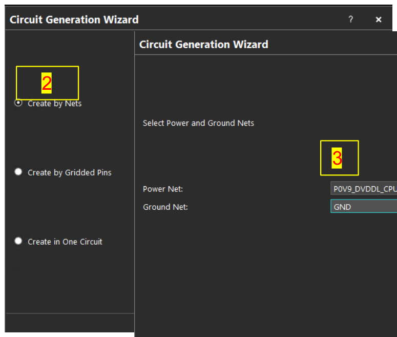
Create by Nets→Next。- 選擇 PWR 與 GND Net →
Next。
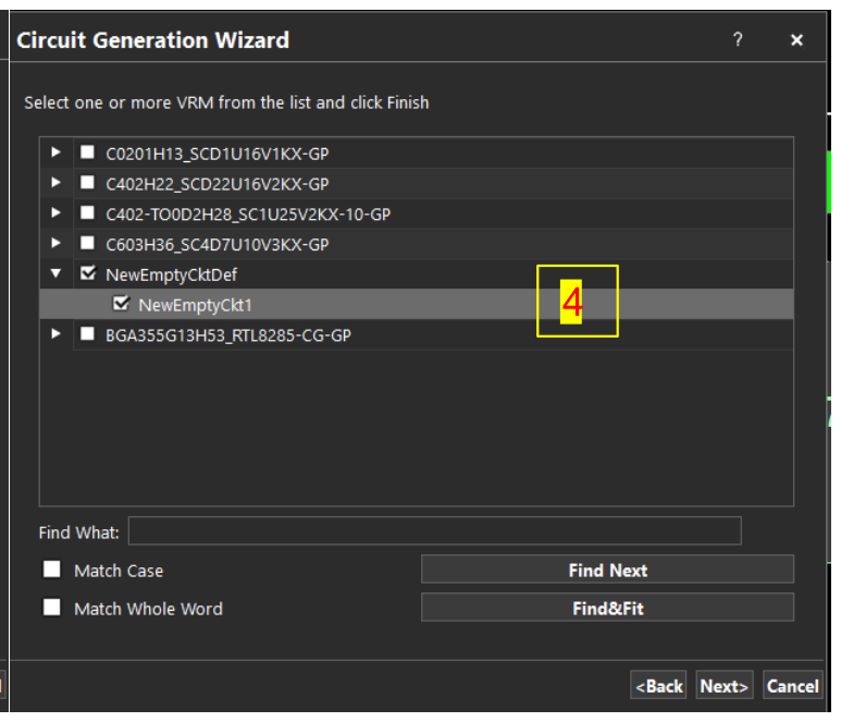
- 選擇
NewEmptyCkt1→Next→Finish。
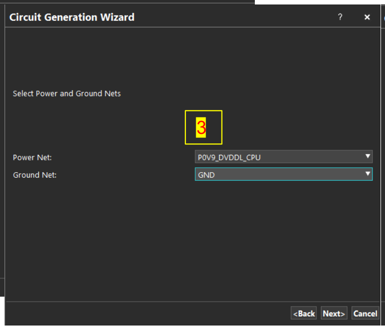
- Select Model Name →
@Short@。