The Era of Hybrid TIM Has Arrived: How Liquid Metal × Silicone is Redefining the Thermal Resistance Limits of Advanced Packaging
The Era of Hybrid TIM Has Arrived: How Liquid Metal × Silicone is Redefining the Thermal Resistance Limits of Advanced Packaging
- Source: SemiVision
- Author: SEMIVISION
- Published: 2025-07-28T11:44:05+08:00
- URL: https://tspasemiconductor.substack.com/p/the-era-of-hybrid-tim-has-arrived The Era of Hybrid TIM Has Arrived: How Liquid Metal × Silicone is Redefining the Thermal Resistance Limits of Advanced Packaging


The Era of Hybrid TIM Has Arrived: How Liquid Metal × Silicone is Redefining the Thermal Resistance Limits of Advanced Packaging
Original Articles By SemiVision Research (IEEE ECTC, Intel , TSMC, Nvidia, Foxconn ,Winston )

Jul 28, 2025
∙ Paid

When discussing the thermal challenges of AI chips, the performance and design of Thermal Interface Materials (TIMs) directly determine thermal resistance and the efficiency of the heat conduction path. This article provides a systematic overview of the mainstream TIM classifications, their physical properties, application constraints, and the impact of structural differences and thickness (BLT) between TIM1 and TIM2 on overall thermal performance.
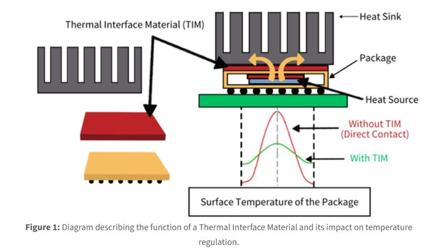
TIMs have evolved from being a passive supporting layer to a critical enabler for system stability in AI processors, high-performance computing (HPC), and next-generation advanced packaging. As chip power densities exceed 2 W/mm², local hot spots surge beyond 100°C, and traditional cooling solutions reach their limits, the choice and design of TIMs often become the defining factor for system performance and lifespan.
Traditionally, TIMs were classified using simple metrics like thermal conductivity, softness, or ease of application. But in today’s advanced packaging context, such definitions are no longer sufficient. It is now essential to consider not only the intrinsic thermal conductivity (κ) of the material, but also:
Bond Line Thickness (BLT)under compression,
Effective contact areawith both die and lid,
Interfacial thermal resistance (Rc),
Modulus stability under thermal cycling, and
Compatibility with multiple assembly and reliability testing cycles.
In recent research from Intel, a hybrid TIM architecture was introduced—combining liquid metal at the center and conformable silicone-based adhesive TIM around the periphery. This design doesn't rely solely on raw material specs but uses thermal and mechanical co-simulation to build a self-compensating thermal interface. The liquid metal handles peak heat flux, while the low-modulus adhesive TIM accommodates warpage and unevenness. A “dam” structure is used to limit flow and stabilize BLT. This architecture significantly reduces junction-to-case thermal resistance while keeping warpage and stress levels within reliability margins. In other words, heat is no longer just dissipated—it is co-engineered into the system architecture.
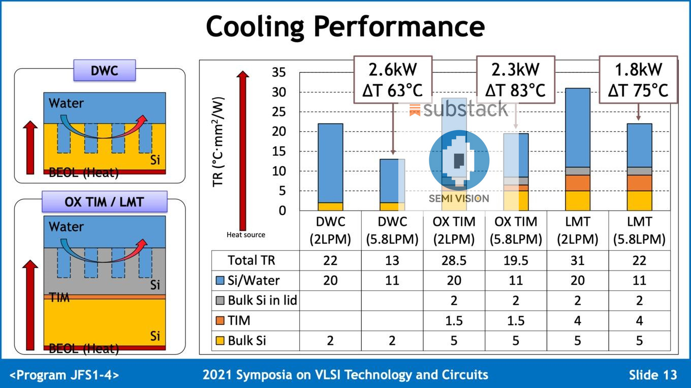
In contrast, TSMC’s mainstream approach reflects a different thermal philosophy: relying on mature polymer TIMs and process stability, while Intel pursues breakthroughs through heterogeneous material combinations and interface-level control. On platforms like CoWoS, InFO, and SoW, TSMC has implemented high-thermal-conductivity TIMs with stable TIM2-to-cold plate interfaces. However, as power density continues to climb, the question arises: Can this bottom-up cooling model scale? Or do we, like Intel, need to rethink interfacial thermal resistance from the ground up?
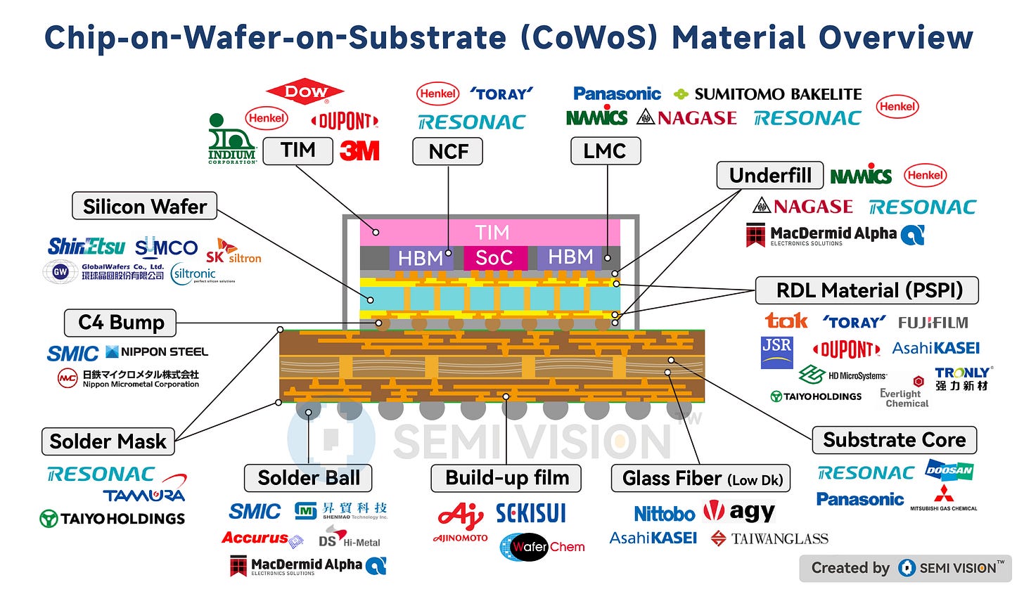

2025年5月1日
This leads to a deeper question:
In an era of generative AI workloads and data center power consumption exceeding hundreds to thousands of watts per server, is one good TIM material enough? Or do we need a system-level thermal interface—co-designed with the packaging platform, thermal module, and even liquid cooling system?
This is the inflection point for thermal engineering: a shift from "selecting a material" to "defining an architecture."
So, if your concern goes beyond stacking chips tighter or running cores faster, and instead focuses on how to make systems last longer within the bounds of heat and mechanical stress, then you won’t want to miss this thermal management revolution that begins with TIM.
Stay tuned for our upcoming SemiVision members-only analysis, where we dive into the next-generation directions for TIM innovation, fundamental differences in TSMC and Intel’s thermal strategies, and real-world examples of co-designed cooling-packaging architectures.

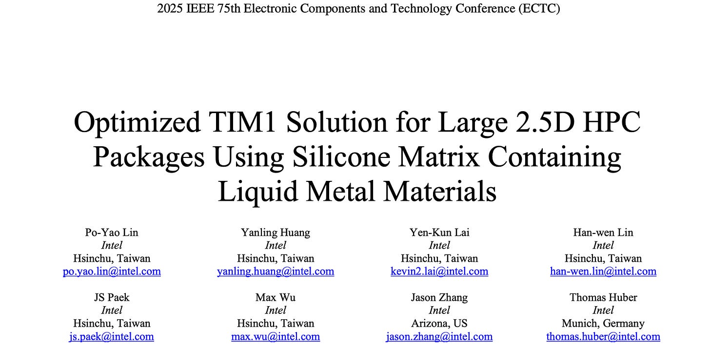
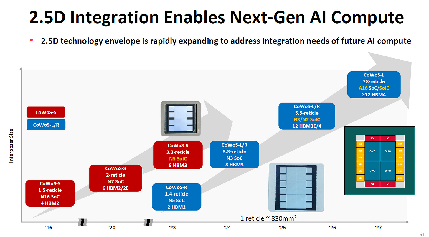
As high-performance computing (HPC) and AI accelerators continue to evolve rapidly, they are pushing power density to unprecedented levels. This trend is particularly evident in 2.5D and 3D advanced packaging architectures, where heterogeneous multi-die integration and large-area fan-out modules create complex and intensified thermal environments.
For Paid Members, SemiVision will discuss topics on
Significance of the Research From INTEL’s results
Background: Power Density & Packaging Trends
Material Rationale: Silicone-Based Liquid Metal TIM
Intel’s Solution: Hybrid TIM Structure with Mechanical Isolation
Simulation and Experimental Results From INTEL
Classification and Characteristics of TIM Materials
TIM1 vs. TIM2: Design Considerations and Thickness Implications
Technology Trends in TIM
Deep Dive into Thermal Interface Materials: Key Mechanisms and Optimization Strategies Behind Thermal Conductivity
Thermal Conductivity: The Fundamental Metric of Heat Transfer Performance
Thermal Resistance: The Key Metric for Real-World Thermal Performance
Practical Strategies for Optimizing Total Thermal Resistance
Fundamental Composition and Mathematical Relationship of Thermal Resistance
Physical Causes and Key Factors of Contact Resistance
Strategies for Reducing Total Thermal Resistance (R_TIM)
Thermal Conductivity ≠ Cooling Performance: The Need for System-Level Co-Design
Application Scenarios and Future Outlook
Liquid Metal TIM: Advantages and Challenges in AI/HPC and Advanced 2.5D/3D Packaging
Thermal Management Architecture and Functional Roles
Application Scenarios and Corresponding Thermal Solutions
Toward Co-Design, Modularity, and System-Level Thermal Optimization
Additive Cold Plate Revolution:Fabric8Labs’ Breakthrough in High-Performance Chip Cooling

The picture illustrates a clear trajectory toward denser vertical interconnect pitches, transitioning from traditional C4 bumps (>100 µm) to µ-bumps (~20–50 µm), and further toward hybrid bonding and SoIC (~1–10 µm) with even sub-micron capabilities in view. This scaling enables higher bandwidth and lower latency inter-die communication but simultaneously increases local power densities and heat flux.
In this context, thermal bottlenecks are no longer confined to system-level cooling infrastructure. Instead, the focus is shifting to the microscale contact interface between chips and substrates—specifically, the first thermal interface material (TIM1). As the primary heat conduction path from die to lid or interposer, TIM1 must now address not only ultra-low thermal resistance but also mechanical reliability under warpage, CTE mismatch, and long-term thermal cycling.
Emerging 3D integration technologies such as SoIC, Foveros, Intel ODI, and M3D—as plotted in the graph—require vertical interconnects below 10 µm pitch. These ultra-fine interfaces drive up the demand for high-performance TIMs capable of maintaining consistent BLT (bond line thickness) and low Rc (contact resistance), even in the face of chip-level warpage and localized thermal hotspots.
Looking ahead, as packaging evolves toward near-memory computing, and logic-to-memory stacks (L1/L2/L3) become thermally co-located, the role of TIM1 becomes central to power delivery integrity, cooling efficiency, and ultimately system-level reliability.
Thus, in the post-CoWoS era, thermal interface materials are no longer auxiliary—they are foundational to the performance and viability of AI and HPC systems.

This study, presented by the Intel team at ECTC 2025, focuses on a hybrid TIM1 solution based on liquid metal fillers embedded in a silicone matrix. The work specifically addresses the thermal and mechanical challenges associated with large 2.5D fan-out lidded package architectures, proposing an optimized material and process design that delivers both high thermal performance and mechanical reliability.
Through dual-domain modeling—thermal and mechanical simulation—the study identifies Bond Line Thickness (BLT) and coverage as critical design targets. It also validates these insights through actual process experiments, demonstrating that by applying dam structures and adhesive-type TIMs at package corners, BLT can be reliably maintained within 50–60 μm, and coverage exceeding 95% can be achieved—significantly outperforming traditional indium solder TIM (STIM) solutions.
Significance of the Research From INTEL’s results
This paper is a breakthrough in overcoming the reliability bottlenecks of liquid metal TIMs in large-area modules. It successfully demonstrates co-optimization of thermal performance and mechanical stability, providing a practical and scalable direction for thermal management in AI servers, data centers, and high-power advanced packaging. It also lays the industrial groundwork for liquid metal and silicone hybrid TIMs in commercial adoption.
The rise of high-power AI and HPC chips—especially those featuring chiplet + HBM integration and large 2.5D fan-out architectures—has made thermal management one of the most critical challenges in 2.5D/3D packaging systems. In this context, the first thermal interface material (TIM1), positioned between the chip and lid, plays a decisive role in determining system cooling efficiency.
This Intel-led research explores the thermal performance, mechanical stress response, and process feasibility of TIM1 in such packages, culminating in a novel silicone-based liquid metal composite TIM with hybrid layout and optimized integration process.
Material Rationale: Silicone-Based Liquid Metal TIM
Liquid metal TIMs (e.g., GaIn, GaInSn) offer exceptionally high thermal conductivity (30–50 W/m·K), far superior to typical polymer-based TIMs (3–10 W/m·K). Their liquid nature allows them to fill micro-gaps at the die interface, drastically reducing interfacial thermal resistance. This makes them ideal for hotspot-intensive 2.5D AI chips, helping suppress Tj,max (junction temperature) rise.
However, pure liquid metal TIMs face several critical challenges:
Chemical reactivity: Corrosive to copper, aluminum, and silver; prone to IMC formation
Oxidation: Rapid Ga₂O₃ layer formation in air degrades contact quality
Fluidity risks: Potential for contamination and shorts; reliability under JEDEC standards remains unproven
Intel’s Solution: Hybrid TIM Structure with Mechanical Isolation
To address these issues, Intel proposes using a silicone elastomer matrix to encapsulate liquid metal, forming a "compressible, thermally conductive, flow-restricted" composite TIM. This design preserves the thermal benefits of liquid metal while mitigating flow and migration issues through silicone’s containment capability.
Further, a hybrid TIM configuration is introduced:
Central zone: Silicone-based liquid metal TIM for peak heat flux handling
Periphery: Adhesive-type polymer TIM (PTIM) and dam structures to stabilize BLT and suppress material flow
The result is a consistent, high-coverage thermal interface between die and lid
Simulation and Experimental Results From INTEL
Simulation results show that whenBLT ≤ 50 μmandcoverage ≥ 92.65%, this hybrid TIM architecture:
Deliverslower junction-to-case thermal resistancethan indium-based STIM
Exhibitsreduced warpageat room temperature
Achieveslower inter-die underfill stress, mitigating delamination risks fromCTE mismatch
Further process validation achieved:
BLT controlat package edges between50–60 μm
95% total coverage
No significant coverage loss at high-power density corners

This study recommends silicone-based liquid metal composites as a next-generation TIM1 solution for high-power AI/HPC applications. The hybrid layout strategy ensures excellent thermal performance, precise process control, and long-term reliability—making it a key enabling material for future high-density advanced packaging.
More importantly, this approach demonstrates how material selection, mechanical engineering, and process design must be co-optimized to overcome the thermal bottlenecks of modern AI infrastructure. As chip power densities continue to rise, thermal interface design will become a defining element of system architecture.

Classification and Characteristics of TIM Materials
1.Polymer-based TIMs
Composition:Silicone, epoxy, polyurethane, etc., embedded with thermally conductive fillers like alumina (Al₂O₃), boron nitride (BN), and carbon black.
Thermal Conductivity:~1–6 W/m·K (depending on filler concentration and dispersion).
Advantages:Soft and compressible; provides gap filling and stress absorption; mature processing; low cost.
Limitations:Relatively low thermal conductivity; prone to reliability issues under long-term high temperatures such as drying, cracking, pump-out, and delamination.
Typical Applications:Used inTIM2(between chip lid and cooling module) or asTIM1for low to mid-power SoCs.
2.Carbon-based TIMs
Types:Graphite, graphene, carbon nanotubes (CNTs), carbon cloth/paper.
Thermal Conductivity:
Graphene:In-plane > 2000 W/m·K (poor through-plane performance).
Graphite paper:Typically 200–600 W/m·K (thickness-dependent).
Advantages:High thermal conductivity, excellent mechanical strength, flexibility, and scalability for thin form factors (<100 µm).
Limitations:Poor vertical heat transfer; high contact resistance at the interface with metal surfaces.
Typical Applications:High-endTIM2, thermal spreaders in laptops/smartphones, certainSoICheat-spreading layers.
3.Indium / Liquid Metal TIMs
Materials:Pure bismuth (Bi), indium (In), gallium (Ga), or alloys such as Ga-In-Sn.
Thermal Conductivity:60–86 W/m·K (Indium ~86; Ga alloys ~70–75).
Advantages:Extremely high thermal conductivity; excellent gap filling capability; suitable for ultra-thin bond lines (<20 µm) and large-area contacts.
Limitations:
Compatibility:Corrosive to common metals like aluminum and copper, requiring surface plating (e.g., Ni/Au).
Cost:High material and process costs; complex reflow and assembly.
Reliability:Prone to delamination or leakage under prolonged high temperature.
Typical Applications:Used inTIM1(between die and lid) or in high-performance thermal interconnects such asHBM stacks.
TIM1 vs. TIM2: Design Considerations and Thickness Implications
TIM1 – Interface Between Chip Die and Lid
Role & Location:
The most critical thermal resistance layer; directly adjacent to the chip’s active layer (junction-to-case).
Requirements:
Transfers high heat flux to the package lid; must withstand extreme thermal gradients and high power density (>300 W/cm²).
Material Selection Criteria:
High thermal conductivity and low contact resistance.
High reliability; resistant to pump-out and aging.
Ultra-thin BLT (typically <50 µm, ideally 10–30 µm) to minimize thermal impedance.
Failure Mechanisms:
Voiding increases thermal resistance.
Delamination, micro-warping, and drying/cracking under thermal cycling.
TIM2 – Interface Between Lid and Heatsink (e.g., Cold Plate)
Role & Location:
Fills the thermal gap between the package lid and external cooling solution.
Requirements:
Must handle large-area heat spreading and compensate for surface roughness and mechanical tolerances.
Material Selection Criteria:
Sufficient softness and conformability.
Tolerable BLT (100–500 µm common) while maintaining thermal performance.
Considerations for reworkability and total system thermal resistance.
Material Examples:
Silicone pads, graphite sheets, paste-based TIMs with ceramic fillers, phase-change materials (PCMs).
Technology Trends in TIM
TIM1: The thinner, the better. However, void control and interface wetting are major challenges. Liquid metal shows promise, but requires plating and careful integration.
TIM2: Can be thicker, but directly impacts cooling module design. Trend leans toward high-conductivity carbon materials or hybrid interfaces.
TSMC, in recentECTCpublications, identified TIM as a primary thermal bottleneck in AI packaging. As a result, they are exploringno-TIM architectureslikemicrochannel-on-dieto bypass this constraint.
Future Outlook:
As power density rises and integration advances, thermal strategies will shift from material selection tosystem-level co-design, aiming to eliminate or embed TIM structures directly within the package—such asburied thermal layersorliquid-cooled microchannels.
Deep Dive into Thermal Interface Materials: Key Mechanisms and Optimization Strategies Behind Thermal Conductivity
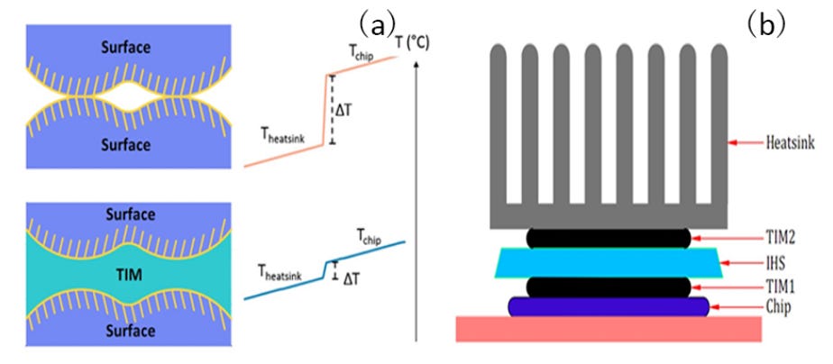
With the growing prevalence of high power density and advanced packaging technologies, the thermal performance requirements for electronic devices have become increasingly stringent. To efficiently transfer heat between chips and cooling components, Thermal Interface Materials (TIMs) play an indispensable role. TIMs fill microscopic voids and air gaps caused by surface roughness between two solid interfaces, establishing a stable and efficient heat transfer pathway. This significantly reduces contact thermal resistance and enhances overall system thermal management.
Thermal Conductivity: The Fundamental Metric of Heat Transfer Performance
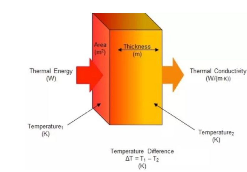
Thermal conductivity is an inherent property of a material, representing its ability to conduct heat. In general, the higher the thermal conductivity, the better the thermal interface material (TIM) can directly transfer heat.
For homogeneous materials, thermal conductivity is an intrinsic attribute and is independent of the material’s size, shape, or orientation—essentially an ideal value. When selecting a TIM, however, one cannot focus solely on thermal conductivity; factors such as hardness, thickness, and heat dissipation area are equally important considerations.
Most TIMs are composite materials, consisting of a polymer matrix embedded with thermally conductive fillers. The polymer matrix offers flexibility, flowability, and adhesion, allowing complete contact with the surface. The fillers, on the other hand, are the primary contributors to thermal conduction.
Common thermally conductive fillers fall into three main categories:
Carbon-based fillers(e.g., graphene, carbon nanotubes),
Metallic fillers(e.g., silver, copper),
Ceramic fillers(e.g., boron nitride, alumina).
Their thermal conductivity, filler loading, particle size, distribution uniformity, orientation, and interfacial compatibility with the polymer matrix are all critical to the overall heat transfer performance. Furthermore, interfacial thermal resistance between filler particles and between fillers and the matrix can significantly hinder thermal conduction.
To address this, surface treatments—such as silane coupling agents—are commonly applied to modify filler surfaces. These treatments enhance filler–matrix bonding and reduce interfacial resistance, therebyimproving overall thermal conductivity. Thisinterfacial engineeringis one of the most crucial methods for optimizing the heat transfer efficiency of TIMs.
Thermal Resistance: The Key Metric for Real-World Thermal Performance
Rt=LkA
While thermal conductivity reflects a material's intrinsic ability to conduct heat, thermal resistance is the most practical and relevant indicator of cooling efficiency in real-world applications. Thermal resistance consists of two main components:
Bulk thermal resistance, caused by the thickness of the TIM material itself.
Contact thermal resistance, resulting from surface roughness and microscopic air gaps at the interface between materials.
Bulk thermal resistance is directly proportional to thickness and inversely proportional to thermal conductivity. Therefore, using a TIM with high thermal conductivity and minimal thickness can effectively reduce bulk resistance. However, in practical scenarios, TIM thickness can vary due to factors such as assembly pressure, substrate warpage, and surface topography.
Contact thermal resistance arises from imperfect contact between mating surfaces. Even surfaces that appear smooth at the macro scale exhibit roughness and microgaps under microscopic inspection. Heat must pass through these discontinuities, which reduces conduction efficiency. Furthermore, coefficient of thermal expansion (CTE) mismatch between silicon dies and heat spreader lids can lead to warpage during operation, further increasing interfacial resistance.
As such, the total thermal resistance in a thermal management system is the sum of bulk resistance from the TIM material and contact resistance from both upper and lower interfaces. This also explains why thermal conductivity alone is not a sufficient metric for evaluating a TIM’s actual cooling performance.
Practical Strategies for Optimizing Total Thermal Resistance
In real-world design and material selection, simply increasing the thermal conductivity of a TIM does not guarantee improved thermal performance. To truly enhance thermal management, it is essential to reduce the total thermal resistance across the entire system. The following strategies can be adopted:
1.Enhance Filler Performance and Distribution Design
Using high-thermal-conductivity fillers and increasing their loading can improve bulk thermal conductivity. However, higher filler content often leads to reduced flowability and processability, which may degrade the conformability and contact quality at the interface.
Thus,striking a balance between filler loading and mechanical propertiesis a critical design challenge.
2.Improve Interfacial Wettability and Adhesion
Enhancing the bonding between the TIM and contacting surfaces increasesactual contact area, thereby reducingcontact thermal resistance. This can be achieved throughsurface treatments,material modifications, andprecise control of assembly pressure.
3.Minimize Bond Line Thickness (BLT)
Reducing the TIM thickness—as long as full coverage and mechanical reliability are maintained—shortens the thermal conduction pathand significantly lowers thermal resistance. This approach placesgreater demands on surface flatness and coplanarity.
4.Reduce the Number of Interfaces in the Thermal Path
In systems with multiple thermal interfaces—such as between the die and spreader, spreader and cooler, cooler and heatsink—each additional interface introduces added resistance. Therefore,simplifying the thermal path and minimizing the number of interfacesis key to improving heat dissipation efficiency.
Thermal interface materials are a core component of modern high-efficiency thermal management systems. High thermal conductivity alone is not enough—the true determinant of performance is total thermal resistance.
Only through co-optimization of material formulation, interface engineering, and packaging architecture can one achieve low-resistance, high-performance thermal modules.
As chip power densities and system integration levels continue to rise, the role of TIMs will become increasingly critical—driving continuous innovation toward higher performance, lower thermal resistance, and improved long-term reliability.
Fundamental Composition and Mathematical Relationship of Thermal Resistance
The total thermal resistance of a TIM (R_TIM) comprises two major components:
RTIM=Rbulk+Rc
R_bulk: The bulk thermal resistance, determined by the material’s thermal conductivity (κ) and its thickness, known as the bond line thickness (BLT):
Rbulk=BLTκ
R_c: The contact resistance, caused by microscopic surface roughness, air gaps, warpage, or uneven pressure at the interface. This is a non-negligible factor in real-world heat conduction scenarios.
Physical Causes and Key Factors of Contact Resistance
Contact resistance arises from the microscale roughness between surfaces such as chips, heat spreaders, cold plates, or heatsinks. These imperfections drastically reduce the actual contact area, introducing gaps and bottlenecks in heat flow. Major influencing factors include:
Surface Flatness and Roughness: Smoother surfaces yield greater real contact area and more efficient heat conduction.
Contact Pressure: Higher clamping force compresses air gaps and enhances interface bonding, thereby reducing R_c.
Elastic Modulus and Conformability of TIM: Low-modulus materials (like liquid metal or silicone) can deform more easily, filling in surface asperities to improve interface heat transfer.
BLT Thickness Control: Thinner TIM layers reduce R_bulk, but require precise pressure distribution to avoid increasing localized R_c due to poor coverage or mechanical instability.
Strategies for Reducing Total Thermal Resistance (R_TIM)
To maximize thermal performance, TIM and packaging design must be optimized in four areas:
(1) Increase Thermal Conductivity (κ):
Enhancing a TIM’s inherent heat transfer ability reduces R_bulk. High-performance fillers like silver particles, aluminum nitride, or liquid metals are effective, but high loading ratios often compromise flowability and manufacturability. Next-gen solutions focus on nanoscale fillers and composite material systems to maintain balance.
(2) Enhance Interface Wetting and Adhesion:
Surface treatments, surfactants, or coupling agents can improve chemical or mechanical bonding between TIM and mating surfaces. For liquid metal TIMs, this is particularly crucial to prevent de-wetting and oxidation failures.
(3) Minimize BLT (Bond Line Thickness):
A thinner TIM layer offers lower R_bulk.
But this demands superior surface planarity and precise application processes. Excessively thin layers can lead to poor coverage or adhesion failure.
Rbulk∝BLT
(4) Reduce Interface Layer Count Along Heat Path:
Each added layer (e.g., thermal pads between lid and cold plate) introduces additional R_c.
Ideal thermal architecture connects the die directly to the main cooling element (like an integrated cold plate), achieving minimal thermal resistance.
。。Rc+Rbulk。
Thermal Conductivity ≠ Cooling Performance: The Need for System-Level Co-Design
Designers often assume that higher κ equals better performance. In reality, chip temperature is governed by total thermal resistance (R_TIM), not conductivity alone.
For instance, halving BLT cuts R_bulk in half, and optimizing contact pressure or interface bonding can reduce R_c by up to 70%. These improvements outweigh merely increasing κ from 10 to 20 W/m·K.
Therefore, TIM selection and design must be co-optimized with the overall package structure, heatsinks, lids, cold plates, and cooling method (air, liquid, or immersion) to meet the stringent thermal control needs of AI, 5G, and 3D-IC applications.
Application Scenarios and Future Outlook
Advanced TIMs are widely adopted in:
High-power chips (Intel Xeon, NVIDIA Hopper, Google TPU)
Multi-die packages (2.5D CoWoS, 3D stacks, fan-out modules)
AI accelerators, 5G RF modules, high-performance networking gear
Cold plate-integrated modules (direct liquid/immersion-cooled data centers)
Looking forward, TIMs will evolve from being mere interface materials to central enablers of system-level thermal strategies. Innovations like hybrid TIMs (liquid metal + silicone), additive manufacturing for cooling channels, and structural co-design are shifting the focus from material specs to architectural integration.
In the era of generative AI, dense integration, and edge computing, thermal design is no longer a secondary consideration—it’s becoming the core determinant of competitive system performance.
Liquid Metal TIM: Advantages and Challenges in AI/HPC and Advanced 2.5D/3D Packaging
I. Advantages
- Ultra-High Thermal Conductivity
Gallium-based alloys such as Ga, GaIn, and GaInSn offer thermal conductivities in the range of30–50 W/m·K, significantly higher than traditional silicones or thermal greases (typically 3–10 W/m·K).
They outperform nearly all polymer-based TIMs, except for indium solder TIMs (71–86 W/m·K), making liquid metals the most promising high-performance materials aside from solders.
- Exceptionally Low Contact Resistance
Due to their liquid nature, these metals can fill microscopic gaps between contact surfaces, dramatically reducing interfacial thermal resistance.
This enables near-ideal heat transfer interfaces, which are critical for managing localized thermal hotspots in AI chips.
- Low Modulus and Mechanical Stress Absorption
Unlike solder-based TIMs with high elastic modulus, liquid metals impose less mechanical stress during thermal cycling.
This reduces the risk of damage between dies and lids and helps prevent delamination or crack propagation caused by coefficient of thermal expansion (CTE) mismatch.
- No Need for High-Temperature Reflow
Liquid metals remain in a fluid state at room temperature, eliminating the need for high-temperature reflow processes.
This minimizes the risk of thermal oxidation and wafer damage, making them suitable for high-density 2.5D/3D stacked modules.
- Potential Reworkability
Unlike cured solder TIMs, liquid metals can theoretically be removed and reapplied, offering an advantage for prototyping and early-stage development where reworkability is crucial.
II. Challenges / Limitations
- Chemical Reactivity and Corrosion Risks
Gallium-based alloys tend to form intermetallic compounds (IMCs) with copper, aluminum, and silver, leading to degradation of electrical and mechanical properties.
Contact with bare copper can result in wetting-induced corrosion or structural breakdown, necessitating surface passivation or the use of inert barrier layers.
- Oxidation and Failure Mechanisms
When exposed to air, liquid metals quickly oxidize, forming compounds like Ga₂O₃ that impair wetting and reduce thermal performance.
Over time, dry-out and migration phenomena may occur, compromising heat transfer consistency and long-term reliability.
- High Fluidity and Process Control Challenges
Their extreme fluidity poses containment risks—liquid metal can overflow into packaging cavities and cause shorts or contamination, especially in multi-die architectures.
Practical applications require companion measures such as adhesive TIMs, physical dams, or sealed cavities to limit movement and ensure BLT (bond line thickness) stability.
- Limited Reliability Qualification
Unlike solder TIMs, which have undergone extensive JEDEC-grade validation, liquid metal TIMs are relatively new in large-area HPC applications.
Comprehensive thermal cycling, temperature-humidity bias, and mechanical shock tests are still required—especially for critical edge and bridge regions in 2.5D/3D configurations where thickness and coverage uniformity are hard to control.
- Material Cost and Supply Chain Maturity
Pure Ga or GaInSn alloys are costly, and their supply chains are not yet standardized for mass deployment.
To reduce cost and improve stability, hybrid mixtures with silicone or gel-based matrices are often used—though at the expense of some thermal performance.
Liquid metal TIMs offer a compelling combination ofexceptionally high thermal conductivityandlow mechanical stress, making them highly attractive for AI accelerators, large HPC modules, and hotspot-targeted thermal management.
However, challenges aroundchemical stability,packaging compatibility, andprocess controlremain. These can potentially be addressed through:
Material innovations(e.g., silicone matrices or self-healing encapsulants)
Structural enhancements(e.g., hybrid TIMs with containment dams)
Packaging co-design strategies(e.g., integration with cold plates or direct die-to-lid paths)
If paired with self-healing packaging materials, advanced passivation layer designs, and reliable encapsulation strategies in the future, liquid metal has the potential to replace solder and high-end thermal greases in specific high-power applications, emerging as a key technology for next-generation thermal interface materials.
Thermal Management Architecture and Functional Roles
- Thermal Interface Materials (TIMs)
TIMs serve the critical role of filling microscopic gaps and surface irregularities between the IC and the heat sink or cold plate, thereby reducing contact thermal resistance. The choice of TIM material directly impacts the overall effectiveness of the thermal conduction path.
Main categories include:
Thermal greases and phase change materials (PCMs):Suitable for CPU and GPU surfaces.
Solid thermal pads:Offer reworkability and mechanical protection.
Compressible high-thermal-conductivity pastes:Used in high-pressure contact zones such as 3D stack interfaces.
Leading suppliers such asHenkelandLairdprovide material solutions with high thermal conductivity, low interfacial impedance, and strong mechanical compliance. They also offer surface affinity enhancements for bonding to metals or ceramics, such assilane coupling agent treatments.
- Cold Plates
Cold plates are the primary components for transferring heat from ICs to liquid coolants in direct-to-chip liquid cooling systems. Traditional cold plates often employmicrochannel structures, but these face challenges in high-power-density environments, such as excessive pressure drop and limited flow channel design flexibility.
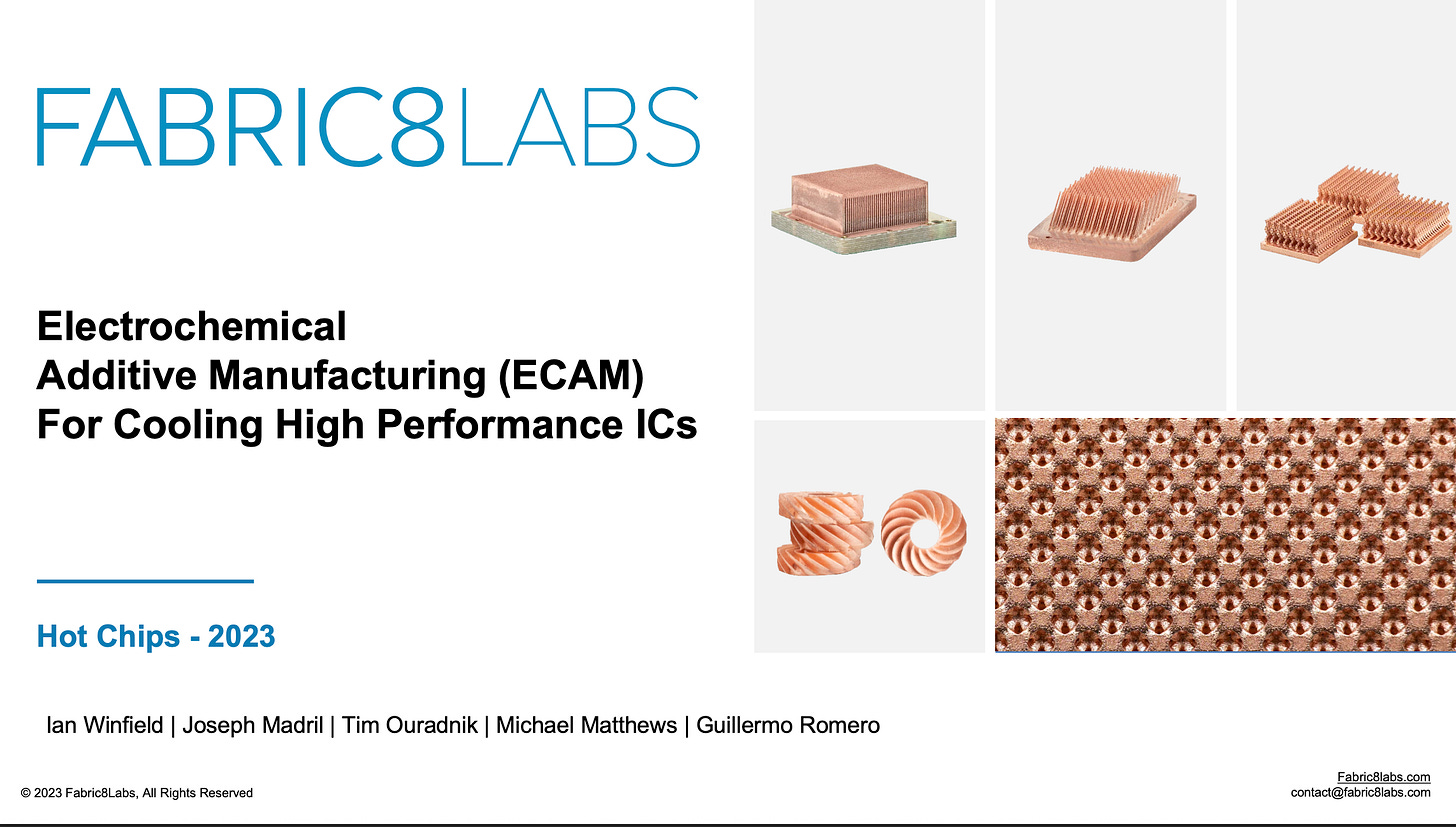
Fabric8Labshas introducedGyroid-structured additive cold platesusing itsECAM (Electrochemical Additive Manufacturing)technology, offering:
Higher surface area and three-dimensional thermal pathways
Tunable porosity to optimize pressure drop and thermal resistance
Customizable geometric topology to match chip stacking and packaging structures (e.g., 3D IC, InFO-L)
Experiments and CFD simulations show that, under the same pump power, Gyroid cold plates can reduce thermal resistance by over35%compared to microchannel designs, and enabletargeted cooling optimizationfor specific hotspot regions.
- Heat Sinks and Heat Exchanger Modules
In air-cooled configurations,heat sinksremain the mainstream solution. Aluminum extruded or die-cast fin structures provide extensive surface area for convective heat dissipation. When paired with efficient TIMs, they are still effective formedium- to low-power modules.
Data center servers typically adopt atwo-stage thermal management architecture:
Stage 1:Cold plates in direct contact with AI accelerators (e.g., GPU/TPU) or HBM stacks
Stage 2:Coolant is circulated throughheat exchangersfor room temperature regulation or waste heat recovery (e.g., cooling towers, liquid cooling walls, immersion tanks)
This multilayer design requires tight integration offluid dynamics, mechanical compliance, and thermal resistance modeling—a hallmark of co-design betweensystem engineering and semiconductor thermal architecture.
Application Scenarios and Corresponding Thermal Solutions
- AI Servers in Data Centers
AI training chips—such asNVIDIA B200orTPUv5—can reach power levels exceeding800W per chip, often configured inmulti-module stacked architectures. Effective thermal management requires a synergistic combination of:
Highly compressible, low thermal resistance TIMs(e.g.,Henkel Loctite TCPseries)
Custom-designed Gyroid cold plates, precisely aligned with chiplet-level thermal hotspots
Dual-loop liquid cooling modulesto accommodate sudden thermal surges and sustained high loads
A real-world implementation of this architecture is showcased byWiwynnandFabric8Labs, featuring:
Modular cold plateswith optimized contact geometry
Detachable TIM carriersfor ease of maintenance
Pressure-balancing modulesto ensure uniform contact across stacked die
This approach reflects a next-generation thermal design paradigm tailored for ultra-high-performance AI servers.
3D IC Packaging and Chiplet Cooling
With TSMC, Intel, and Samsung advancing heterogeneous integration technologies—such asInFO-L,Foveros, andH-Cube—the vertical stacking of chiplets introduces significantlocalized thermal accumulation. Addressing this thermal bottleneck requires a multi-faceted strategy:
Localized high-conductivity TIMs combined with thermally conductive layers(e.g.,AlN,SiCfillers). In many papers presented at the ECTC forum,metal layer dispositionis also discussed as an effective technique for lateral heat spreading within stacked die structures.
High-permeability cold plate structures, such asmicro-Gyroid lattices, are well-suited for non-uniform stacking regions. However,microchannel cold plate designpresents significant engineering challenges due to the complex interplay offluid dynamics and thermophysical properties. Cooling flow must be driven by pressure differentials, and modeling often starts with theHagen–Poiseuille equation, extending into2D/3D thermal-fluid simulations. Yet,temperature-driven effectsandsurface tension phenomenaintroduce non-linearities that complicate the analysis and require advanced CFD (Computational Fluid Dynamics) techniques.
Thermal expansion matching between TIM and cold plate materialsis crucial to avoidstress fatigueanddelaminationduring prolonged operation. Mismatches in the coefficient of thermal expansion (CTE) can lead to mechanical degradation, especially under cyclical thermal loading, makingmaterials engineering and stress-relief designa key pillar in reliable 3D IC cooling.
TSMC InFO Package Cooling Interface
TSMC’s InFO-L package, a fan-out 2.5D design, features a reduced package height, significantly limiting the vertical space available for cooling structures. The optimal thermal management approach for InFO-L includes:
High thermal conductivity, low-compression TIMs: The thermal interface material must possess alow compression modulusto conform to ultra-thin interfaces without damaging delicate structures.
Cold plate thickness under 1 mm, with geometrical adaptability: Cooling plates fabricated throughadditive manufacturing(e.g., lattice or Gyroid topologies) offer design flexibility to accommodate the compact and irregular footprint of InFO packages.
Integrated pressure regulation and resonance damping mechanisms: These improvemechanical stability, reduce vibrational stress, andmaximize effective contact areabetween the cooling structure and the InFO-L package.
Toward Co-Design, Modularity, and System-Level Thermal Optimization
As system-in-package (SiP) complexity and computational workloads increase,thermal design has become a system-level imperativerather than an afterthought. Future thermal architectures for AI and high-performance systems will embody three key traits:
- Interface Co-Design
Effective heat removal demandsmaterial and mechanical co-engineeringacross the TIM, cold plate, and packaging layers. Proper interfacial coupling is essential to minimize thermal contact resistance and to prevent delamination or mechanical fatigue during thermal cycling.
- Modular Thermal Platforms
Cooling modules must bereworkable, scalable, and application-specific, allowing rapid servicing and flexible adaptation to diverse chiplet configurations and power maps. This modularity accelerates deployment and improves overall thermal lifecycle management.
- Co-Optimization of Process and Structure
Additive manufacturing (AM) techniques unlock structural freedom, enablingcold plates with tailored flow pathsandgeometry-matched surfaces. When combined withconformable, high-performance TIMs(e.g., stencil-printed or coated types), this results inoptimized thermal pathwaysand enhanced interface performance.
In an era of escalating power density and packaging integration,thermal engineering is no longer peripheral—it is mission-critical. The next generation of thermal solutions must embrace a holistic approach, integratinginterface material science, microfluidic cold plate engineering, and advanced packaging heat transfer modeling. Only through such cross-disciplinary innovation can we meet the demands of future AI and HPC systems.
Additive Cooling Revolution: Fabric8Labs’ Breakthrough in High-Performance Chip Thermal Management
As AI accelerators, FPGAs, and HPC processors continue to push the boundaries of power consumption—often exceeding 800W per chip—the demand for high-efficiency cooling architectures has reached a critical threshold. Traditional microchannel cold plates, while once sufficient, are increasingly constrained by high pressure drops, thermal resistance bottlenecks, and limited design flexibility in handling extreme heat flux densities and non-uniform thermal profiles. In response to these challenges, Fabric8Labs has pioneered a transformative approach through additive manufacturing, unveiling its gyroid-structured cold plates atHotChips2023 and 2024, and redefining the future of thermal solutions for advanced packaging and high-performance ICs.
Additive Cold Plate Revolution: Fabric8Labs’ Breakthrough in High-Performance Chip Cooling
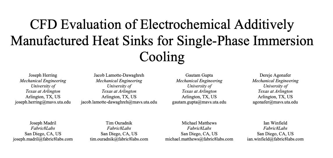
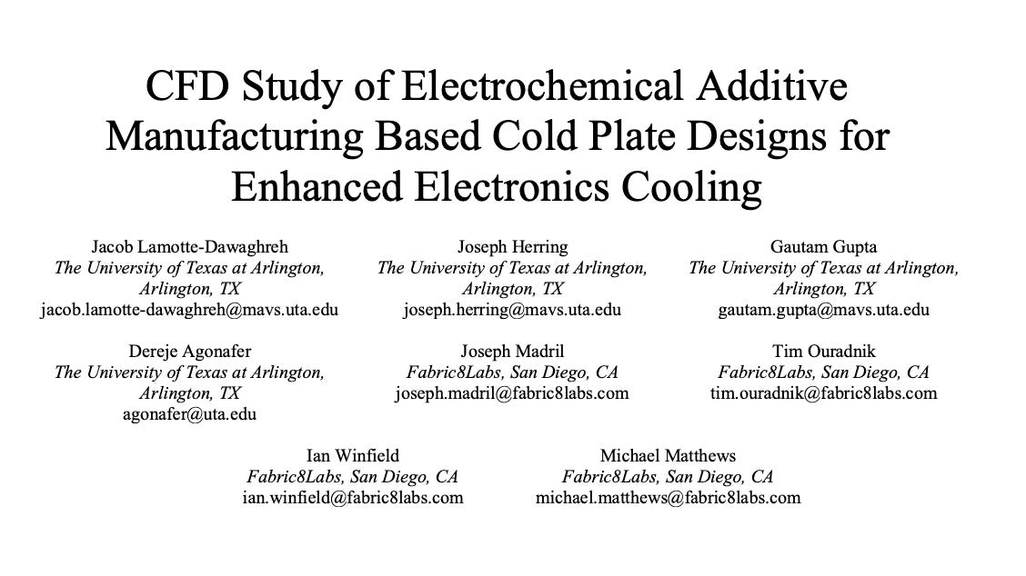
As power consumption in high-performance components such as AI accelerators, FPGAs, and HPC processors continues to rise, conventional microchannel cold plates are increasingly strained under the demands of extreme heat flux. These traditional designs face inherent limitations, including high pressure drop, constrained thermal resistance, and limited design flexibility when adapting to evolving packaging topologies. In a series of presentations at HotChips 2023 and 2024, Fabric8Labs unveiled a new class of cooling technology built uponadditive manufacturing (AM), featuringgyroid lattice structures. This innovation opens up a transformative thermal management path for advanced packaging and next-generation ICs.
Through their electrochemical additive manufacturing (ECAM) platform, Fabric8Labs constructsconformable, high-surface-area cold platesthat directly address the spatial, thermal, and mechanical challenges of AI and HPC systems. By leveraging thetriply periodic minimal surface (TPMS)geometry of gyroid structures, these cold plates offer significantly enhanced heat dissipation efficiency while maintaining low fluidic impedance. Their flexibility in geometry also enables tight integration with chiplet architectures, non-planar die surfaces, and compact 3D IC stacks.
In essence,Fabric8Labs’ additive cold plates represent not only a materials and process innovation, but a fundamental redesign of how cooling systems are co-engineered with the chip and package. This approach supports higher power density, improves system reliability, and paves the way for scalable, modular, and application-specific thermal platforms across future AI infrastructure.
Gyroid-Based Additive Cold Plate Design Concept
At the core of Fabric8Labs’ cooling solution lies the use ofElectrochemical Additive Manufacturing (ECAM)to construct a three-dimensional continuous surface topology known as thegyroid structure. This architecture enables significantly higher surface area and fluid channel density within the same form factor, resulting in enhanced thermal performance for high-power electronic packages.

II. CFD Benchmark: Gyroid Cold Plate vs. Microchannel Cold Plate
In a comprehensive set of simulations and physical validations, Fabric8Labs conducted comparative CFD analyses of gyroid-structured cold plates and traditional microchannel cold plates across a range of flow rates (0.5 LPM to 1.5 LPM). Sensitivity studies on porosity and wall thickness were also performed to identify performance tipping points.
- Thermal Resistance Superiority
Under equivalent flow conditions, gyroid cold plates consistently demonstrated significantly lower thermal resistance than microchannel designs. Notably, at 65% porosity and 266 μm wall thickness, the gyroid topology exhibited a clear thermal advantage. Further simulations revealed that reducing porosity to 50% and wall thickness to 100 μm could lower thermal resistance by more than 35%—even when the flow rate was halved—indicating robust cooling potential even under constrained hydraulic conditions.
- Pressure Drop and Flow Tradeoff
However, this improvement comes with a tradeoff. Compared to microchannel cold plates, gyroid cold plates experienced substantially higher pressure drops at the same flow rate—on average, a 113% increase. This implies that with a fixed pumping system, the attainable flow rate through a gyroid structure may be reduced by half due to elevated fluid resistance.
Despite this, Fabric8Labs emphasized in their findings thatat equal pumping power(where lower flow is offset by higher pressure), the gyroid cold plate still outperforms the microchannel equivalent in cooling effectiveness—thanks to its superior thermal contact and efficient heat transfer pathways.
III. Optimizing Porosity and Geometric Design
The studies also revealed that thermal resistance continues to decrease as porosity drops below 65%, reaching a minimum at an optimal threshold. However, excessive densification leads to severe hydraulic constraints, increasing pressure drop and reducing overall efficiency. This points to the existence of adesign sweet spot, where thermal performance and fluidic resistance are optimally balanced.
This insight redefines cold plate design paradigms—not merely optimizing materials or flow channels, but enablingco-design of heat and fluid pathwaysat the micro-architectural level through topological control and additive fabrication.
IV. Value Proposition of Additive Cold Plates
Fabric8Labs’ gyroid cold plate architecture introduces several critical advantages:
Superior Thermal Resistance at Constant Pumping Power
Even under flow-limited conditions, gyroid structures consistently outperform microchannel cold plates in cooling efficiency.
Enhanced Design Freedom and Packaging Conformity
With ECAM’s precise form control, custom-shaped cold plates can be produced to match irregular or asymmetric IC packages.
Future-Readiness for Advanced Packaging and Chiplet Architectures
As chiplet-based designs proliferate—characterized by compact footprints, high heat fluxes, and multi-source hotspots—gyroid cold plates offer zonal thermal targeting and tunable impedance pathways to address localized cooling demands.
These advantages position additive cold plates as a strong candidate for next-generation thermal interface solutions in high-power semiconductor applications, especially in an era where both power densities and packaging complexity are accelerating in tandem.
I. Thermal Management for AI Data Center Servers
At Computex 2025,Fabric8LabsandWiwynnshowcased an ECAM-based cold plate engineered for high-power AI accelerators. This design leverages 3D gyroid topology to optimize coolant flow paths based on chip-level heat distribution, achieving up to48% higher thermal performancecompared to conventional skived microchannel cold plates. Third-party CFD analysis confirmed that under identical pump power, the gyroid structure achieveslower total thermal resistanceandmore effective temperature control, especially in high heat flux data center environments. Owing to its geometrical tunability, the cold plate can be customized to match localized SoC heat maps, adjusting flow width and porosity, thus enhancing overall system stability and energy efficiency.
II. Cooling of 3D-IC High-Density Packages
3D-IC packaging introduces stacked dies and concentrated thermal hotspots, posing significant cooling challenges. Previous studies indicate that conventional water-cooled cold plates can reduce 3D-IC temperatures to the range of39–50 °Cunder high heat flux. Fabric8Labs’ ECAM process allows the gyroid structure to featuremicron-level wall thicknessandhigh porosity, enabling precise alignment with die-level hotspots and uniform thermal distribution. Compared to traditional linear channel designs, this architecture offers improved thermal control and superior integration flexibility.
III. Application in TSMC’s InFO-L Packaging
TSMC’s InFO-L (Integrated Fan-Out-Low) is an advanced, compact 2D/3D fan-out packaging platform. Gyroid cold plates can be tailored to match InFO’s specific heat source distribution, especially covering thermally intensive areas such as RDLs and TIVs. The high-resolution conformal cooling provided by these cold plates effectively mitigates local thermal bottlenecks and aligns with the thermal requirements of high-performance multi-chiplet modules, making them ideal for InFO-L implementations.
IV. Co-Design Strategy with TIM Vendors such as Henkel and Laird
Thermal Interface Integration:Henkel and Laird, as leading TIM providers, can apply high-performance thermal greases or phase change materials directly onto the gyroid metallic surface with micron-scale conformity. This improves interface contact between cold plates, chips, and heat sinks.
Interface Resistance Optimization:The high surface area of the gyroid topology can be further enhanced using surface primers such as silane coupling agents from Henkel, significantly reducing the contact resistance (R_TIM) at the interface.
Mechanical Compliance Co-Design:The mechanical properties of TIMs, especially compressibility, must be tuned to align with the cold plate’s porosity and flow resistance. Collaborative formulation and thickness control between Henkel/Laird and ECAM design ensure uniform compression and optimal interface adherence under operating pump pressure.
V. Design Guidelines and Future Outlook
Localized Porosity Tuning:The gyroid topology enables spatially variable porosity, which can be adapted to InFO-L’s heat distribution pattern forthermal-zone-aware cooling.
Porosity Optimization Window:It is recommended to maintain porosity between50–65%to balance flow rate and pressure drop, while selecting TIMs that combinehigh thermal conductivitywithelastic compliance.
Modular Cold Plate Architecture:Segmenting thermal zones (e.g., HBMs, GPU/AI cores) with dedicated cold plate modules enhances maintainability and design reusability—ideal for scalable data center deployments.
Pump and Heat Recovery Integration:Given ECAM cold plates maintain low thermal resistance despite increased pressure drop, they can be integrated with Wiwynn’s liquid loop infrastructure forheat reuseorside-stream cooling strategies.
We will continue to conduct an in-depth discussion on Intel’s latest research, along with a comprehensive analysis of the global supply chain for TIM (Thermal Interface Material) solutions.


PreviousNext
TopLatestDiscussions






See all